In VCO there is oscillator. There is thousands type of oscillators : Wien bridge oscillator, Phase-shift oscillator, avalanche transistor oscillator. However, all oscillators are not usuable for a VCO, indeed, some are quite difficult to control depending on the voltage.
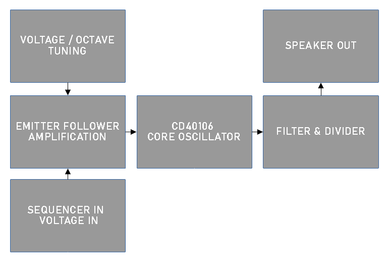
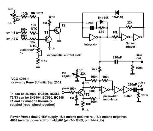
For this VCO, I re-used the idea of Moritz Klein which took it from René Schmidt based on the CD40106 IC chip. The architecture of this VCO is describes of the left and the schematics on the right comes from René Schmitz:
 |
 |
|---|
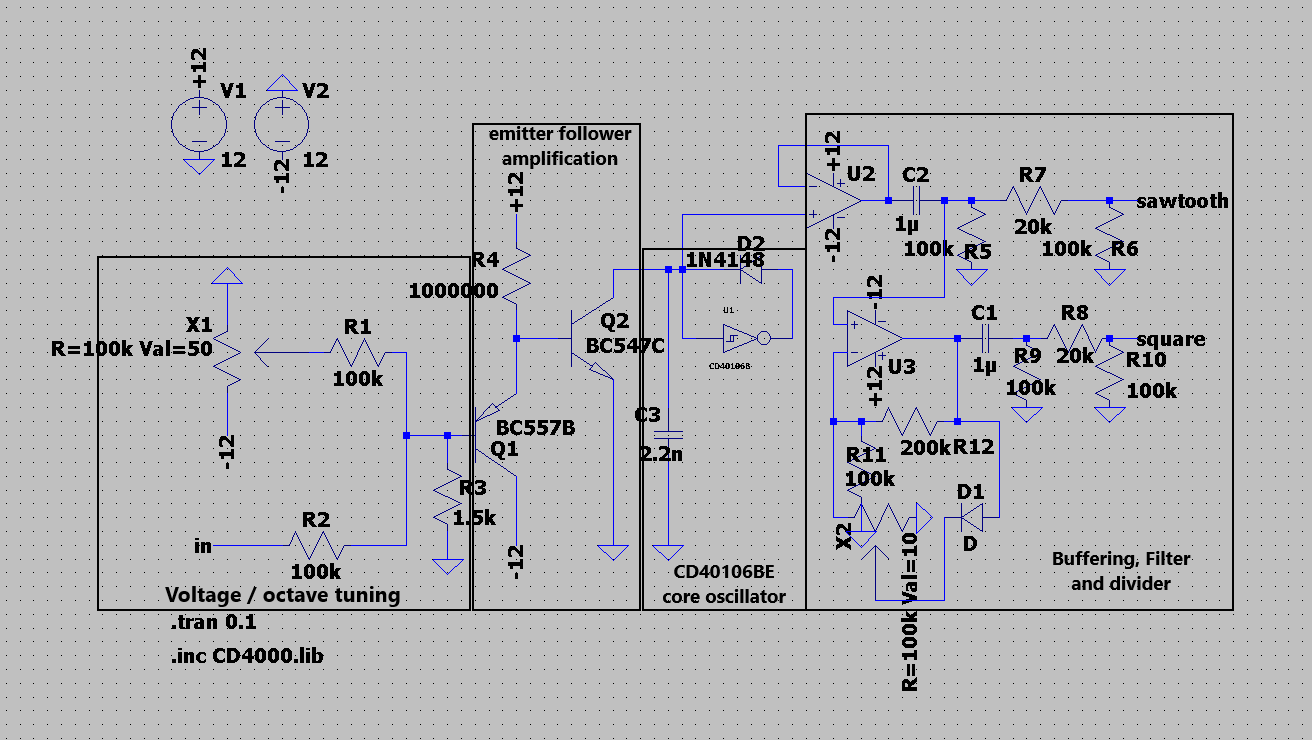
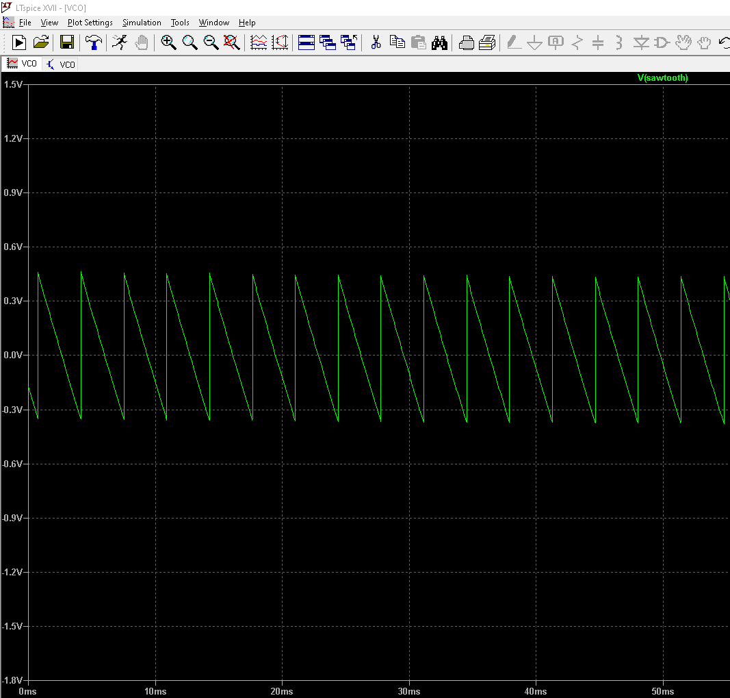
After some modifications, like replacing the other schmidt Trigger inverters with OP-Amps, a simulation can be launched on LT-SPICE to see if it really works:
 |
 |
|---|
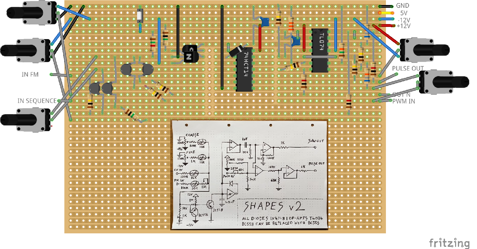
It seems good enough to build up a prototype. The first manufacture will be on a breadboard and we will do it on the software Fritzing.
The circuit has to look like the same as the schematic and the size of the board has to be optimised depending on the size of the module (128.5 x 46.4 mm). The breadboard soldering will NOT be done in one time.
At the beginning I did directly the schematic from Moritz Klein (left image below) in one go and i was just disappointed when I set the voltage up : Nothing happened and I lost a CD40106 chip. At this stage, going into a reparation process can be quite long. I tried to find where the probable short-circuit was but start again from the beginning is also the best way to not losing time. This is also a good reason to have a method for the manufacture process.
It has to start from the core oscillator, then testing and validating the proper behaviour. During the welding process, every add component/system can delete the oscillation function if it not done properly. The strategy is actually to verify if the circuit is still working after every additionnal block or set of components.
 |
 |
|---|
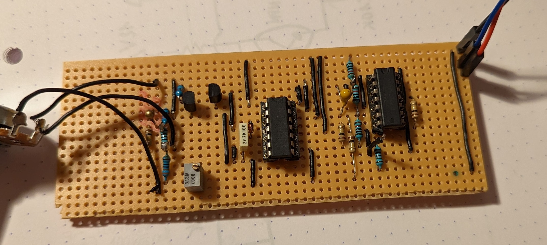
Finally, on the right image above we can see the prototype.
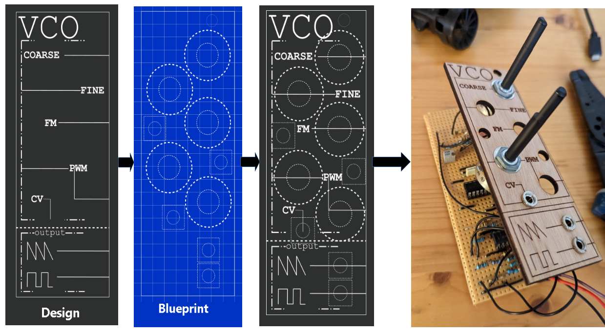
The last step to do is to design the interface of the module with the eurorack norm. The next image shows both the "style" of the design and the blueprint (mechanical) which makes the final product. I will use wood to form the module and a laser writer for the fonts/lines all from a FABLab in my town.
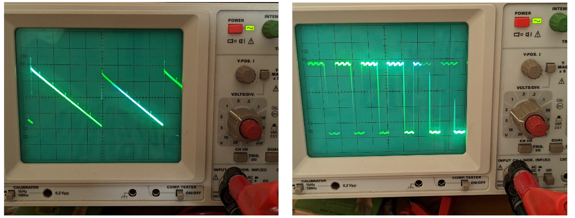
The module is done and we can checked on the oscilloscope. We have a saw tooth signal and a square but there are weird : There is some peaks on the decreasing saw tooth and waves on the squares... It is because of my homemade power supply which is not the best for now, as a result there is still some clipping issues but at least it is still functionnal